Tunneling Sensors
Comprehensive models and feedback control analyses have been developed at our
lab to improve the performance of tunneling sensors. Both linear and nonlinear
models of the tunneling transducers are considered to simulate our sensor
performance and enhance the sensor performance in the new design. A sample
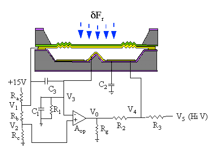
modeling and control analysis for the most basic tunneling sensor feedback
circuit is shown below.

Where C1 and C2 are stray capacitance, C3 is the equivalent capacitance between membrane and tunneling tip.
According to the early work on the Scanning Tunneling Microscope (STM), the current due to the tunneling of electrons across a narrow barrier of width x is given by :

where  is the effective height of the tunneling barrier, x is the
shortest distance between the tunneling electrodes. This is similar to the
relationship of voltage and current in a diode. As an approximation, the diode
allows no current to flow if less than 0.6 Volts is across it. However, if any
current is flowing, only 0.6 V is dropped. This same relation holds for the
classical switch: if not in contact, no matter the separation, no current
flows, and if any current flows, the electrodes must be in contact.
A more detailed physical model of the voltage to current relationship of a diode is an exponential. If just under 0.6 V is applied, a small amount of current will flow. The current changes exponentially according to bias voltage. Similarly, if the electrodes of the switch are slightly separated, about 10 Angstroms, a small tunneling current will flow. The tunneling current varies exponentially according to junction separation. We incorporate this Quantum Mechanics phenomenon, electron tunneling, into designing micromachined tunneling sensors.
Because the tunneling current is highly nonlinear in nature, it is necessary to use feedback circuitry to control the tunneling separation. We use force-feedback to maintain the separation at roughly 10 Angstroms to extend the linear range. The exponential relationship between tunneling current and junction separation grants highly sensitive displacement detection. It allows miniaturization of the sensors without losing sensitivity.
The setting on a high voltage power supply is manually increased until some current begins to flow through the tunneling junction. When this current exceeds the setpoint of 1.5 nA, the op-amp begins to lower its output, so that the sum of the op-amp output and power supply is adjusted to keep the tunneling current equal to 1.5 nA. If an external signal force is applied to the membrane, the feedback circuit reacts by producing a balancing force so as to keep the current constant.
The following block diagram conceptually illustrates the linear model of the tunneling sensor. G1 represents the dynamics of the circuit between tunneling tip and op-amp. Aop represents the dynamics of op-amp. G2 represents the dynamics of the circuit between op-amp and deflection electrode.

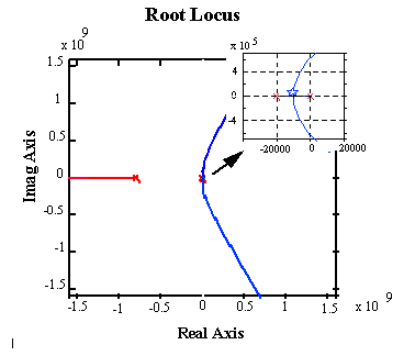
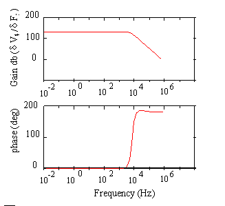
The root locus and simulated frequency response are shown below for the linear model. We can check the stability, bandwidth etc. for the system, tunneling sensor with feedback circuit, from these plots. Since the operating point is located around the star mark, the system is stable with feasible electronic elements. The closed loop poles on the root loci show how to approach wider bandwidth because the distance between closed loop poles and origin represents the system bandwidth.


This simulation predicts a bandwidth of 10 kHz which is in agreement with the measured bandwidth for the tunneling sensor with this basic feedback circuit. From the modeling and control analysis, the physical limitations for bandwidth are observed.
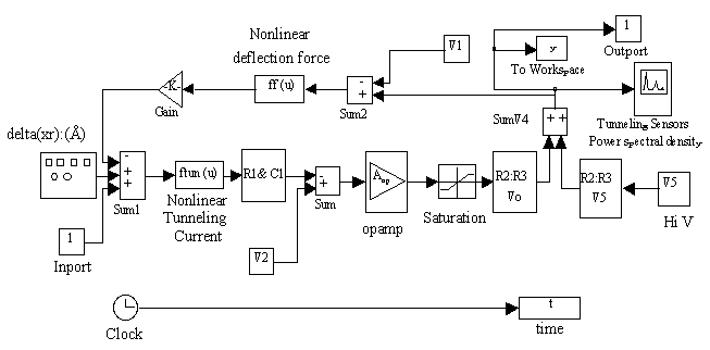
In addition, a nonlinear model has been constructed within SIMULINK as shown below.

The nonlinear SIMULINK model was constructed to simulate larger input signal response. It considers nonlinearities due to electron tunneling, electrostatic re-balance force and saturation of electronic components.
Several different feedback control circuits and tunneling sensors have been fabricated, studied, modeled, and tested at our lab. LQG is used to do optimal control design. Both analog and digital control designs are under study. Finite element analysis and Laser Vibrometer are also utilized to design and test micro-mechanical structures.