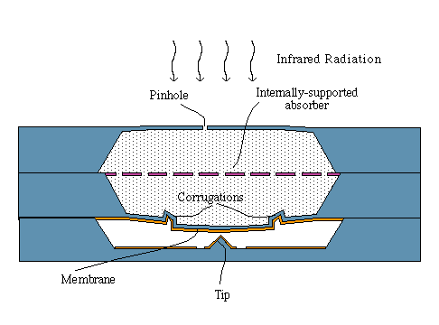

When the sensor is exposed to an IR signal, the absorber retains the thermal energy and heats the gas. Since the gas is essentially trapped for high frequency signals, by the Ideal Gas Law the pressure of the gas must increase. This pressure on the membrane applies a force, causing the membrane to deflect. As discussed in the general description of our tunneling sensors, we can measure the force on the membrane, which is a measure of the change in IR signal.
Prototype devices based on this design have been operated with NEP better than 0.3 nW per root Hz. This is competitive with the best comparably sized uncooled sensors available. Click here to learn more about how we're using and testing our IR sensors.
Download a paper about the physics of our tunneling sensors (Word 5.1, 250k)
Download a paper about the physics of our tunneling sensors (RTF)