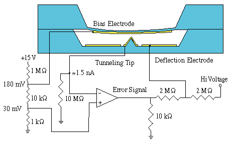
The above picture shows the most basic circuit used to operate our tunneling sensors. Other circuits use the same approach.
A slight biasing voltage(roughly 150 mV) is applied between the membrane and the tip. Bringing the two together with this potential difference allows tunneling current to flow. The current that does flow causes a small voltage drop across the 10 M resistor. A roughly 1.5nA current causes the voltage at V- of the Op-Amp to match V+.
When the sensor is not tunneling, V- is at ground. Since V+ is greater than V-, the output of the Op-Amp goes towards the positive rail. As a result, the voltage at the Deflection Electrode increases. Larger Deflection Voltages pull the membrane closer to the tip, which allows more tunneling current to flow. More tunneling current raises the voltage at V-, which brings the two Op-Amp inputs closer to the same potential.
Similarly, if too much current is flowing, V- is larger than V+. The Op-Amp goes to its negative rail, lowering the Deflection Voltage, which allows the membrane to move further from the tip. Since the membrane is further from the tip, less tunneling current flows, bringing the two Op-Amp inputs closer to the same potential.
The appropriate Deflection Voltage for proper separation of the membrane and tip drifts slowly over time. Our group is studying this Low Frequency Drift, but in the mean time we adjust the Hi Voltage supply. For the basic circuit, we turn the knob on our power supply when the Op-Amp ceases to operate properly. These adustments are neccessary roughly once an hour. When adjusted properly, the 15V swing out of the Op-Amp is ample to control the sensor and respond to the high frequency signals.
Thus, our circuit has a high frequency control(the Op-Amp) to respond to the signal, and a low frequency control(the Hi Voltage supply) to respond to drift of the Deflection Voltage needed. Other circuits have been developed to try and automatically control the Hi Voltage.
The next successful circuit used a Hi Voltage supply that was fixed at 500 V. The error signal was filtered and then used to control a Hi Voltage transistor, which modulated the voltage at the point labelled Hi Voltage. This circuit also used positive feedback, so the Error Voltage measured when no signal was present would vary as the neccessary Defection Voltage changed.
Our next iteration used a DC-DC converter that goes from 5V or 12V to 500V. It has a linear relationship so for the 5V-500V converter, a 4V input causes a roughly 400V output. We exploited this fact by low pass filtering the Error Signal with a very long time constant. We then feed this Voltage to an integrator, whose output is the input to the Voltage Converter. Thus, if there was a DC offset to the Error Signal, the integrator will adjust the Hi Voltage supply until there is no DC offset. While there is no offset, the integrator maintains the Hi Voltage supply voltage. The major drawback of this circuit is that the integrator is very slow, so at startup it takes a long time for it to raise the Hi Voltage so tunneling occurs. Once it starts operating, though, this circuit works well. A major advantage is that regardless of the Deflection Voltage needed, the Error signal always oscillates around ground.(Note, this circuit uses a dual supply Op-Amp powered with +/- 12 V. This requires slight adjustment of some of the resistors. This circuit is being used in our study of Low Frequency Drift.