» Motivation and Background
Capacitive pressure sensors are known to have superior performance to piezoresistive presure sensors in terms of their package stress sensitivity and temperature dependence. However, the signal readout circuitries for capacitive pressure sensors are a lot more complicated due to their small signals, nonlinearities, and susceptibility to RF interference.
» Sensor Development
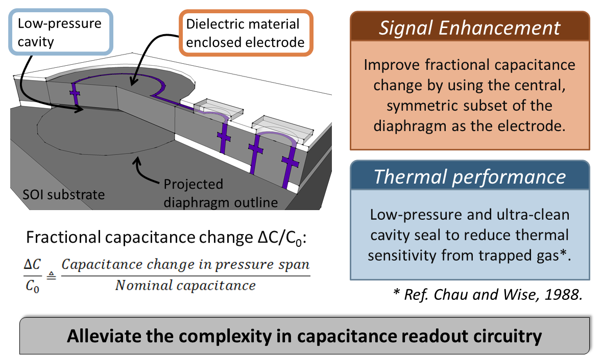
One way to address the issue of circiut complexity resulted by small signal is to use only the central portion of the diaphragm as the capacitive sensing electrode. By decoupling the electrode area from the diaphragm area and using a reduced electrode size, the fractional capacitance change can be increased. From circuit design standpoint this means less analog gain required prior to A/D conversion and as a consequence the system can have lower noise.
Another important aspect of the sensor performance is its sensitivity to temperature variations. Temperature sensitivity arises from thermal expansion of the materials, thermal mismatch, and the expansion of the gases trapped in the cavity. Sealing the cavity in a low pressure and high temperature enviornment can efficiently reduce the impact from the trapped gases and is our approach to reduce temperature sensitivity.
The low temperature sensitivity together with the enhanced fractional capacitance change will alleviate the complexity in capacitance readout circuit design.
» Device Fabrication
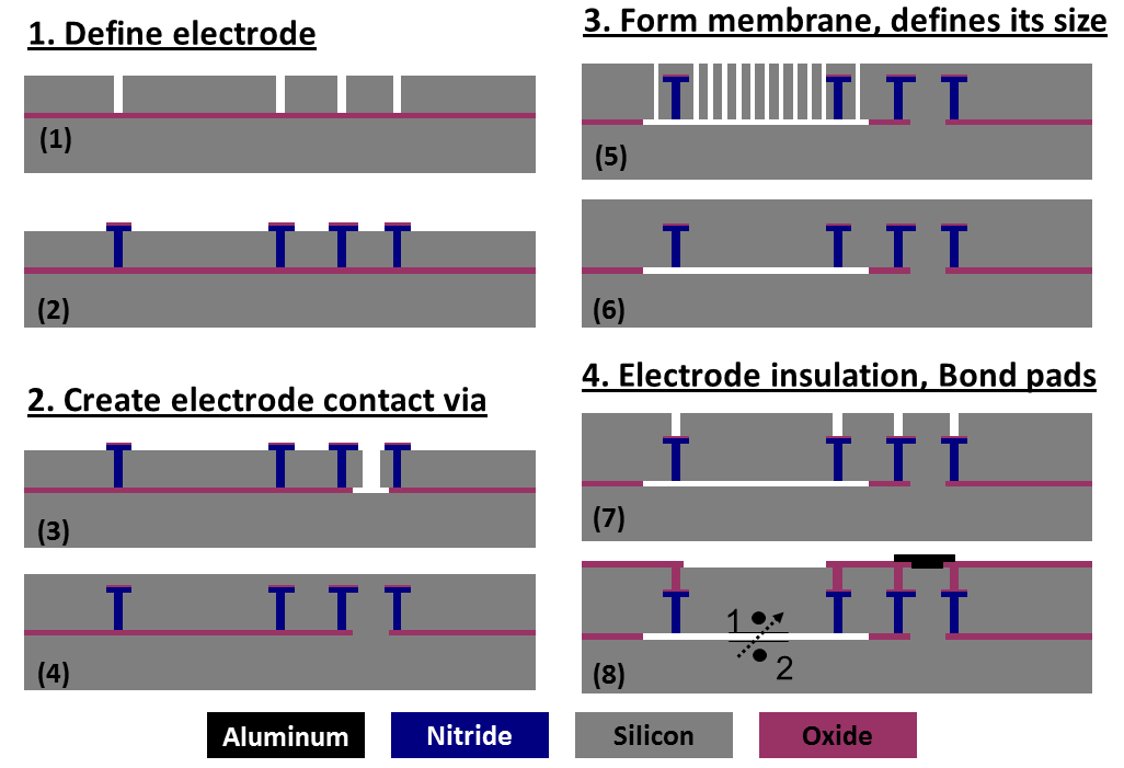
The aforementioned pressure sensors are fabricated using nitride-refilled trenches to isolate the top (deformable) electrode from the bulk silicon diaphragm. Epi-seal technology developed in our group has been utilized to create the cavity in the capacitive sensor, which realizes (1) small device footprint and (2) ultra-clean and low-pressure cavity left as fabricated.
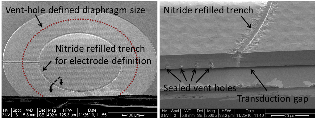 SEM images of a fabricated pressure sensor. Left: Overview of the capacitive diaphragm. Red dotted circle highlights the perimeter of the diaphragm defined by the placement of vent holes. Right: Enlarged view across the nitride-refilled trench showing the transduction gap, the sealed vent holes, and the nitride-refilled trench for electroode isolation.
 » Characterization
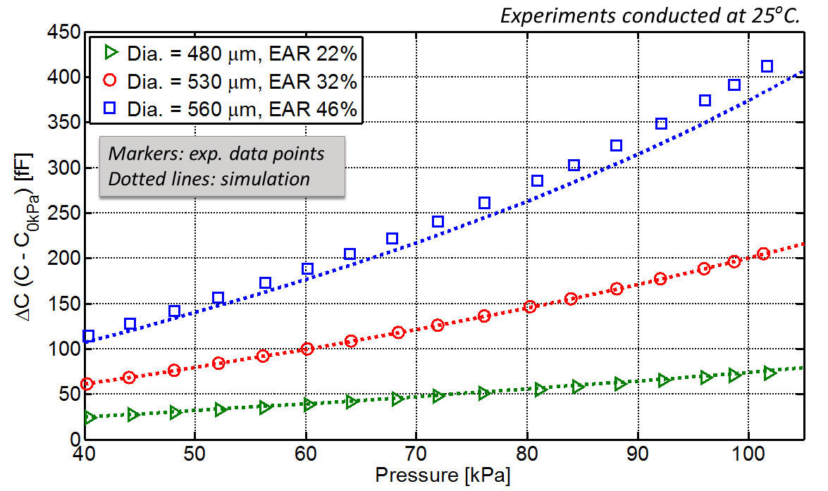
The pressure to capacitance difference relationship for three devices with various sizes in diaphragm and electrode areas is shown below, where Dia. represents the diaphragm diameter and EAR represents the ratio of electrode area to diaphragm area. Comparing the experimental and simulation results, the deviations could be attributed to process variations in diaphragm dimensions. Extracting the sensitivity of the devices with least square fit, the errors are within 10%.
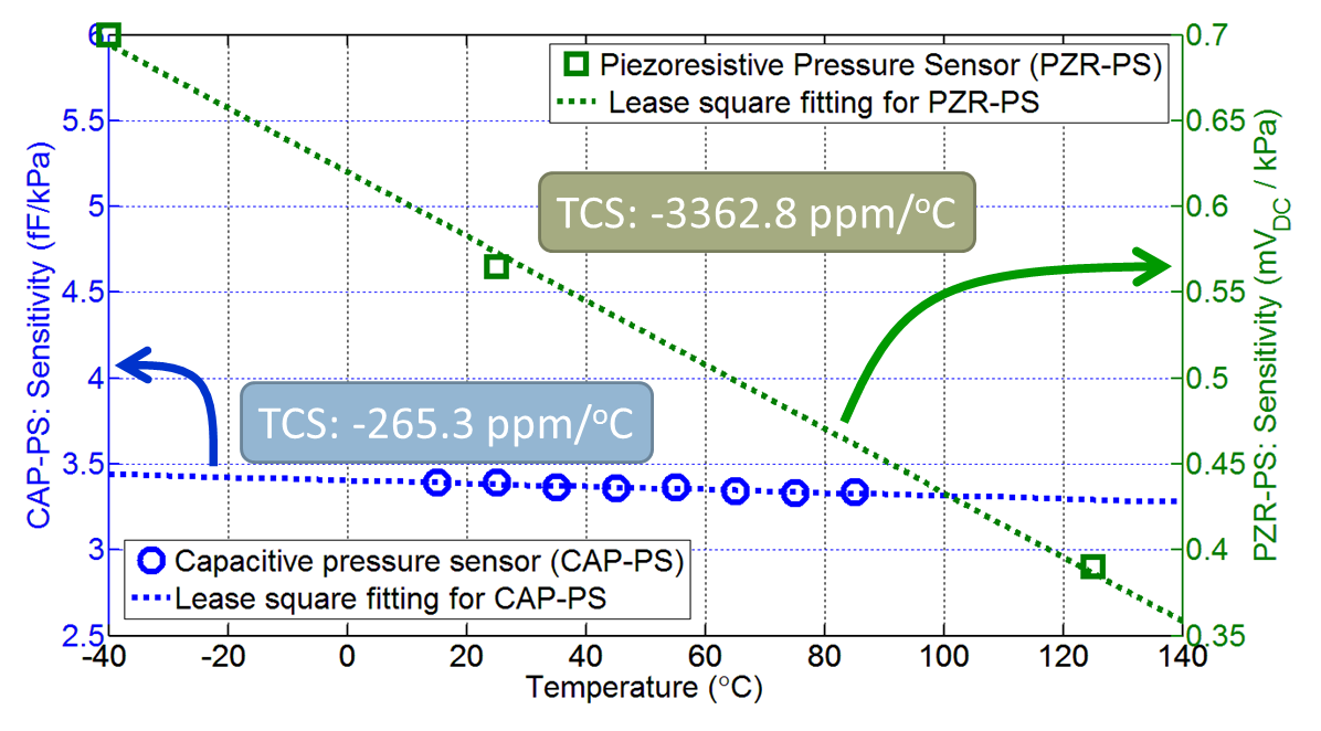
Comparing our device with a commercially available piezoresistive pressure sensor which has similar operating range, the preliminary result shows that when both sensors are not temperature compensated and for the temperature range we tested, the temperature coefficient of sensitivity of our capacitive device is 10 times better than the piezoresistive pressure sensor.
» Reference and Acknowledgement
Reference
- H.-L. Chau and K. D. Wise, "An Ultraminiature Solid-state Pressure Sensor for a Cardiovascular Catheter," IEEE Transaction on Electron Devices, vol. 35, No. 2, p. 2355-62, 1988.
Related publication
- C.-F. Chiang, A. B. Graham, M. W. Messana, J Provine, D. T. Buchman, G. J. O'Brien, T. W. Kenny,"Capacitive Absolute Pressure Sensor with Independent Electrode and Membrane Sizes for Improved Fractional Capacitance Change," The 16th International Conference on Solid-State Sensors, Actuators and Microsystems (TRANSDUCERS '11), Beijing, China, pp. 894-897, June 5 - 9, 2011.
Acknowledgement
This work is supported by Bosch research and technology center at Palo Alto, USA.
Thank also goes to David Christensen for some of the art work in this webpage.