 |
|
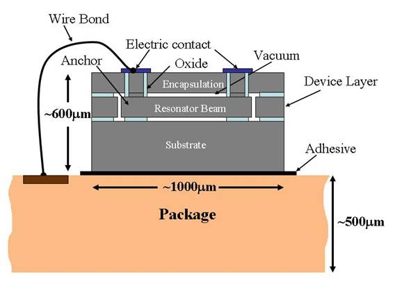
Figure 1 -
Schematic of a typical MEMS resonator chip attached to a package
with adhesive |
|
 |
|
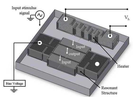
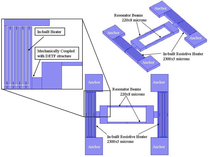
Figure 2 -
Isometric view of the device layer of the chip which contains
resonant structure with input-output electrodes and a resistive
heater. The thickness of the device layer is 20mm.
The resistive heater is used to ovenize the device for temperature
control to compensate the temperature dependence of the resonator
frequency. However this type of heater is not thermally isolated and
hence leads to high power consumption. |
|
|
  |
|
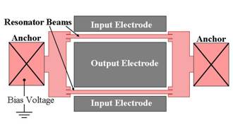
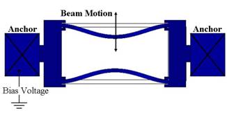
Figure 3 -
Top view of double ended tuning fork (DETF) type resonant structure.
FEM simulation of flexural vibration mode of a DETF (exaggerated
view).
|
|
 |
|
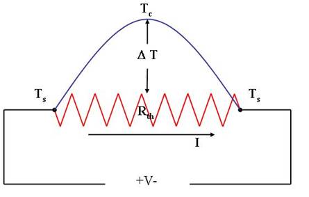
Figure 4 -
Temperature profile along the length of a current carrying resistive
heater having thermal resistance of Rth and electrical
resistance of Re. The above temperature profile shows
that if the resonator is attached at the center of the heater, it
will maximize heating and minimize heat loss, thereby leading to
reduced power consumption for the same temperature rise. |
 |
|
Figure 5 -
Resonator design with local thermal isolation. The heater is
in-built to the DETF such that the resonant structure is attached at
the center of the heater. The entire structure is released except at
the four anchors. |
 |
|
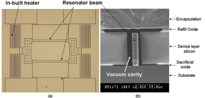
Figure 6 - (a) Optical image of the top view of the
fabricated device before the deposition of the encapsulation layer.
(b) SEM view of the cross-section of a resonator after the
deposition of the encapsulation layer. |
 |
|
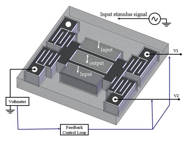
Figure 7 -
Isometric view of the device layer schematic showing the DETF with
the in-built heater. A stimulus signal is applied to the input
electrode. Heating voltages V1 and V2 are
controlled using feedback control loop to maintain a constant bias
for the resonator. |
 |
|
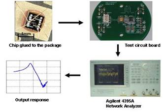
Figure 8 -
Schematic of the test setup for frequency measurement. The device
after being attached into the package is soldered in a PCB to
conduct sweep measurement experiment to get a frequency output
response. |
 |
|
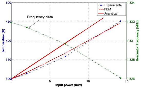
Figure 9 - Variation of resonator frequency due to
joule heating of the in-built heater. The decrease in frequency
(right y-axis) in the above plot corresponds to a temperature rise
(left y-axis, pre-calibrated) with increasing input power.
Experimental results are compared with theoretical estimation. 1-D
analytical results give an upper bound as it is a measure of maximum
temperature at the center of the in-built heater whereas the FEM
output corresponds to the temperature at the center of the resonator
beams. |
 |
|
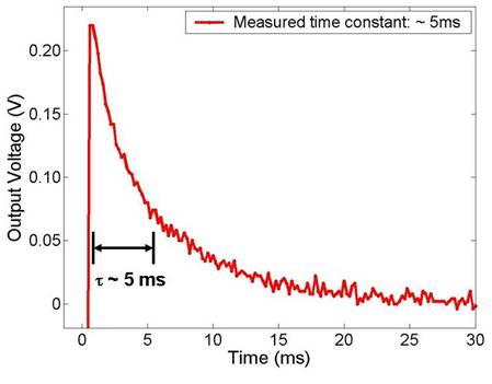
Figure 10 - Thermal
response of resonator with in-built heater. Time constant of
approximately 5 ms was measured using wheatstone bridge with an
input pulse of 4V at 10Hz and a DC offset of 0.5V. Y-axis represents
change in heater resistance due to cooling. |
 |
|
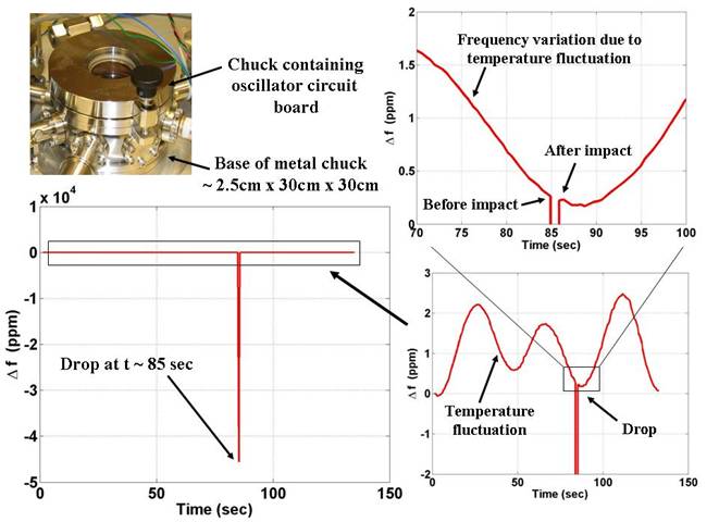
Figure 11 - A
drop test resulted in a temporary change in frequency at the time of
drop. This test is done to check the flexibility of the in-built
heater. In order to increase the thermal isolation, the thermal
resistance of the heater should be as large as possible, however
this also leads to a flexible structure which reduces the mechanical
stability of the resonator. The above drop test confirms that in
spite of large thermal resistance, this structure is mechanically
stable. |
| |
|
An efficient heat delivery and thermal isolation mechanism for a
MEMS resonator has been demonstrated. The in-built heater based
thermal isolation technique serves a dual purpose of localized
heating and thermal isolation, thereby providing maximum heating
with reduced input power. At the same time the device has a small
thermal time constant and high impact resistance because of its
miniature design. Compared to the commercially used quartz crystals
(1-10 Watts and around 30 minutes warm-up time), this work has
demonstrated orders of magnitude improvement in power dissipation
and thermal time constant with a potential for further improvement.
Furthermore this method is simple enough to implement it into any
existing MEMS fabrication process. The described design of
micro-oven is highly suitable for temperature stabilization of
micro-resonators and for very precise control of frequency (< 1.0
ppm) over a large temperature span. |
Supported by the DARPA HERMIT Program |
 |
|