|
|
MAT-Testmicromechanical
|
| MAT-Test is a new method for characterising the mechanical properties of thin films. MAT-Test is being developed in the MEMS research group at the Department of Engineering at Cambridge University, UK. This page presents a brief summary of the MAT-Test method. |
| MAT-Test |
| Introduction and Overview | |
|
Commercially viable MEMS device design and manufacture requires knowledge of the material properties of the materials that are used in the design. The majority of materials available to the MEMS designer are thin films (e.g. silicon nitride, polysilicon), single-crystal substrates (silicon, quartz), or amorphous substrates (glass, plastic). These materials, because of their sample size and/or production methods, are difficult to measure using traditional macro-scale testing methods. As a result, the reported values for mechanical properties of these materials vary widely and are not generally applicable [1]. MAT-Test is a testing method for measuring key material properties of thin films. The test method is based on beam bending: a surface profilometer is used to apply a force to free-standing microbeam test structures constructed from the material under test (MUT). Young's modulus, fracture strength, and Poisson's ratio of the MUT can then be determined from the force applied by the profilometer, the geometry of the test structure, and the resulting deflection of the test structure. A novel interpretation of the microbeam bending data allows the extracted parameters to be determined with high accuracy. MAT-Test is easy to perform and requires only standard microfabrication laboratory equipment, unlike other methods (e.g. tensile test, nanoindentation). We have chosen to pursue a bending method over alternative methods such as resonant frequency measurement or tensile testing because it is the easiest method to implement in terms of fabrication of test structures and recording of data. A bending methodology based on surface profilometers was chosen because they are an inexpensive, easy-to-use piece of laboratory equipment that is found in every IC and microtechnology laboratory. MAT-Test uses the profilometer capabilities in a novel manner that provides superior performance over previously published methods. The most popular controlled bending methods that have been published previously rely on nanoindenters, which are expensive and rare. We believe that the combination of common equipment, ease of use, performance, and general applicability will allow the widespread adoption of MAT-Test both in Research, for characterisation of new materials, and in Manufacturing, for process quality control. The name "MAT-Test" has two meanings: first, it is a shortening of the phrase "Materials Testing". Second, it is a reference to the "E-Test" used in the IC industry to characterize transistor production processes. It is also an acknowledgement of the "M-Test" thin film test methodology described by Osterberg and Senturia [2], which was itself named after E-Test. |
|
|
References: [1] Schweitz, J.-A., Mechanical Characterization of Thin Films by Micromechanical Techniques. MRS Bulletin, July 1992. 17(7): p. 34-45. [2] Osterberg, P.M. and S.D. Senturia, M-TEST: A test chip for MEMS material property measurement using electrostatically actuated test structures. Microelectromechanical Systems, Journal of, June 1997. 6(2): p. 107-118. |
| Theoretical Analysis | ||||||
|
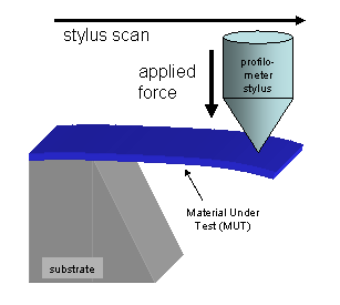
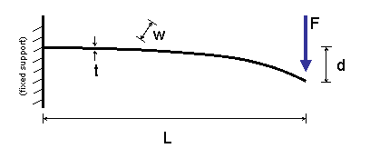
The theoretical basis for the MAT-Test measurements is based on the nature of the data recorded by a contact surface profilometer as it travels along the length of a suspended cantilever (Figure 1).
The deflection experienced by the end of a beam under these conditions can be described by the Euler small-deflection equation:
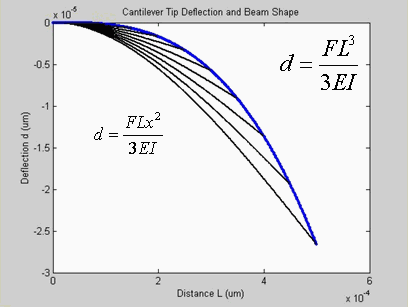
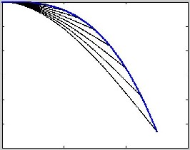
The data from the surface profilometer is a collection of deflection measurements from the tip of many cantilevers. It is, in essence, a plot of the Euler equation. It is not a plot of the shape of a loaded cantilever. The two shapes are plotted for comparison in Figure 3.
There are many non-ideal effects or errors that cause the measured deflection of the cantilever to deviate significantly from the deflection predicted by the Euler equation. These errors include:
Young's Modulus The data recorded by the surface profilometer is d as a function of L. If we perform a fourth-order polynomial curve fit to the data, we get a function that looks like: The error effects are represented by the other coefficients, and do not affect the extraction of Young's modulus. We are investigating whether other information can be extracted from the other coefficients, but the other bending effects are more difficult to isolate. Fracture Stress Fracture stress can also be evaluated with the surface profilometer. The stress, sigma, in the bending cantilever is given by: Poisson's ratio Poisson's ratio can be determined from a comparison of a thin film and a thick film of the same material. The effective Young's modulus of the thin film is affected by the stiffening effect, which is a function of Poisson's ratio. The effect of stiffening on the thick beam is negligible. Therefore, a comparison of the Young's modulus values as measured by the method described above will yield Poisson's ratio.
|
| Simulation | ||||
|
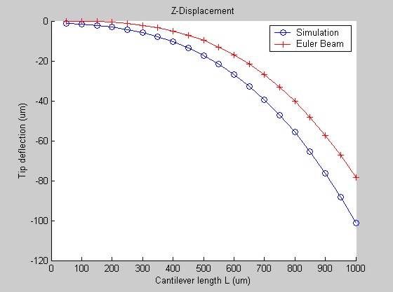
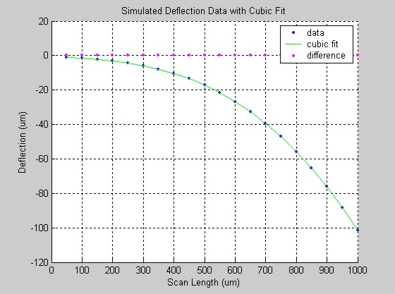
Finite-element simulations of cantilevers bending under MAT-Test conditions have been perfomed using FEMLAB, and finite element simulation package for MATLAB. The results support our analysis: the bending error effects are separate from the bending coefficient, Y. Figure 4 shows a plot of simulated beam deflection from a beam whose root support condition is a large plate, simulating the undercut typical of a cantilever created by wet-etching of a silicon substrate. Figure 5 shows the third-order fit to the simulated data- it is very good!
|
| Results and Future Work | |
|
The work described here was submitted as a thesis toward the MPhil degree by Matthew A. Hopcroft in December 2002. The Academic Supervisor was Dr. David Moore. You may request a copy of the thesis from the author: hopcroft AT stanford DOT edu. A second student, Johnny H. HE, is working on expanding the capabilities of MAT-Test. |