Stanford University seal

High-Stability Silicon MEMS Resonators

FEM animation of a tuning fork resonator sine wave animation

"[it is desired to have] a Watch to keep Time exactly: But, by reason of the Motion of a Ship, the Variation of Heat and Cold, Wet and Dry, and the difference of Gravity in different Latitudes, such a Watch hath not yet been made."

Sir Isaac Newton, report to the House of Commons, 1714


Micromechanical resonators that exhibit very small changes in resonant frequency over a broad temperature range and high stability over time are desirable for communication and navigation applications. This page presents some results from my PhD research towards this goal. For more information, please download my Ph.D. dissertation.
October 2007

Encapsulated Micromechanical Resonators

The first consideration for high-stability resosnators is long term stability. We accomplish this by fabricated encapsulated resonators using the "epi-seal" fabrication process [1]. In the epi-seal process, micromechanical silicon resonators are fabricated in single crystal silicon and encapsulated with epitaxially deposited polysilicon. The structures are defined by deep reactive-ion etching in a silicon-on-oxide (SOI) wafer, released with a HF vapor etch, and then encapsulated by epitaxial silicon deposition. The resonators, sealed in a low-pressure, hermetic cavity, exhibit good performance (MHz resonance, 10e3 Q) and the silicon die are robust enough for standard IC dicing and handling. Silicon resonators that are fabricated in this process exhibit no measurable long-term drift or burn-in [2], which is quite remarkable. The resonator designs chosen for these experiments are double-ended tuning forks (DETF), shown below. Each beam of the tuning fork measures 220 x 20 x 8 µm, and the device has a resonant frequency and quality factor (Q) of approximately 1.3 MHz and 10,000 respectively at room temperature. The resonators are actuated and sensed electrostatically. Figures 1 - 4 illustrate the structure of a typical resonator.

Schematic of silicon tuning fork resonator
Figure 1 - A single-anchored double-ended tuning fork (SA-DETF) micromechanical resonator.
cross-section diagram of epi-seal process
Figure 2 - Encapsulated resonator cross-section diagram.
Cross-section SEM of epi-seal resonator
Figure 3 - Cross-section SEM, corresponding to the diagram in Figure 2.
Rendering of silicon tuning fork resonator
Figure 4 - Rendering of the SA DETF. The metal lines and electrical vias are shown. The surrounding encapsulation layers are represented by the transparent box.
Resonator Temperature Sensitivity

The resonant frequency of an electrostatic DETF is sensitive to its environment and its electrical operating conditions. Some of the most significant parameters are:
ParameterEffect on Frequency
Axial Stress No limit
Dimensions ~1.2 ppm/C
Stiffness ~30 ppm/C
Acceleration 1e-3 - 1e3 ppm/g
Electrical Conditions
(bias voltage)
1e2 ppm/V

These parameters can have complex dependencies on each other and on environmental conditions, such as acceleration, humidity, temperature, etc. Temperature is the most significant environmental variable, as it can affect all of the frequency parameters through various mechanisms: thermal expansion, material softening [3], accelerated chemical reactions, and so on. The result of these effects is that the resonant frequency of the resonator changes significantly with temperature; this is called the temperature coefficient of frequency (TCf). The results of a typical TCf measurement of one of our resonators is shown in Figure 5.

TCf measurement of a silicon resonator
Figure 5 - Typical results of a TCf measurement of a SA DETF silicon resonator. After following best practice design guidelines (below), the TCf is dominated by the material softening of silicon.
Resonator Design for Reduced TCf

There are several design features that can reduce or eliminate the frequency sensitivity of a silicon resonator. First, and most important, is to package it in a robust enclosure with a clean operating environment. This is accomplished in our process using epitaxial deposition of silicon to encapsulate the resonator. This deposition process is performed at elevated temperatures (~ 1000 C) which serve to break down any contaminants that might have survived the prior chemical cleaning steps. The resulting enclosure is hermetic, with very low gas diffusion into the enclosure, and strong enough to survive plastic injection-molding (100 psi).

Second, the DETF structure is suspended in space inside the encapsulation from a single anchor point. If the DETF has an anchor at each end of the beams (a "double-anchored" or DA structure), differential thermal expansion of the materials in the system can create axial stress in the beams. This stress can have a strong and unpredictable effect on the resonant frequency. A single-anchor (SA) DETF is largely immune from these effects.

Third, the mass of the resonator is minimized. This is a natural consequence of using silicon MEMS technology, and results in reduced acceleration sensitivity and makes the encapsulation process easier.

Fourth, the number of materials in the system is minimized. Different materials can have different coefficients of thermal expansion (CTE) or hysteretic temperature characteristcs. Adding materials to the system increases the complexity and potential for undesirable interactions exponentially. Metals in particular often have unrepeatable performance with temperature.

Resonator Design for Compensated TCf

It is also possible to design resonator structures that use competing temperature effects to compensate for changes in temperature and reduce the TCf. For example, we can use differential thermal expansion to create an axial stress which increases the resonant frequency with increasing temperature. At the same time, the material of the DETF beam is getting softer with increasing temperature, which reduces the resonant frequency. We can imagine a structure where these two effects can cancel out, resulting in a reduced or even near-zero TCf. Many variations on this theme have been published, both in our group and by others [4,5,6]. However, none of these designs have yet been shown to have long-term viability. Typically, the introduction of additional temperature sensitivities causes as many problems as it solves.

A promising recent development from our research is the use of silicon dioxide coatings to compensate the temperature response. Silicon dioxide has the unusual property of becoming harder as temperature increases. Silicon has the more usual property of becoming softer at higher temperatures. A composite beam of silicon and silicon dioxide can have a very small change in stiffness, and hence frequency, with temperature [7].

Resonator Temperature Control

It is clear that variations in temperature are a significant problem for resonator frequency stability. Even with the best design practices, we will still have a non-zero TCf over a practical operating temperature range. The obvious answer, then, is to stabilize the temperature of the device. We can achieve a significant reduction in complexity if, instead of heating and cooling the structure in response to changes in the ambient temperature, we simply heat it to a temperature above the highest ambient temperature that we will encounter and adjust the heating power as necessary to maintain the resonator temperature. In order to do this, we require a means of heating the device and sensing its temperature.

Heating the resonator is most easily accomplished by simple joule heating of a resistor on or near the device. If we incorporate a resistor into the anchor, we also gain thermal isolation from the surrounding environment, which reduces the heating power required to achieve a given temperature above the environment. For example, the Spring Resistor (SR) design is shown in Figure 6. The folded springs at each end of the device serve as thermal isolation, resistive heaters, and as mechanical isolation from the substrate.

The SR ovenized silicon resonator
Figure 6 - Spring Resistor (SR) resonator schematic. Folded springs at each end of the DETF resonator provide thermal and mechanical isolation. The effective thermal isolation of the resonator from the ambient is ~10e3 K/W.

Temperature sensing is somewhat more difficult. The ideal temperature sensor would consume zero power, provide an output signal perfectly correlated with the temperature of the resonator, and have no noise. Candidates include: external Pt thermistors mounted on top of the resonator encapsulation, resistors formed by local doping on or near the resonator, the electrical resistance of the resonator structure. However, all of these have some significant drawbacks. Fortunately, there is another option. Because of the geometry and material properties of our silicon resonators, the quality factor (Q) is limited by Thermoelastic Damping (TED) [8]. TED is a temperature-dependent phenomenon, and so the Q of the resonators is a strong function of temperature [9]. The magnitude of the resonator displacement at resonance is proportional to Q, and the amplitude of the output signal is proportional to the resonator displacement. Therefore, we can use the amplitude of the resonator output as a temperature sensor. This is a nearly ideal signal- it consumes no power and is directly correlated with the temperature of the device [10].

Plot of Q vs T
Figure 7 - Typical plot of resonator Q vs Temperature. The Q change is ~1%/C.
Frequency Stability

For constant-temperature operation, the resonator can be operated with automatic temperature compensation using a lookup table-based control scheme (Figure 8) or a feedback control loop using a temperature sensor. For lookup table, or calibration-based, control, the frequency response of the device to applied heating power is measured at different temperatures. This data is used to create a look-up table of frequency versus applied power at different temperatures. The temperature is measured, and the appropriate heating power is applied. For the SR design shown above, the variation of the resonator frequency can be reduced to < 1 ppm over a -55 - 85 C range using 15 mW of heating power (Figure 9). For comparison, commercially available high-performance Oven Controlled Crystal Oscillators (OCXO) can achieve stabilities of 0.4 ppb with 5 W of power [12].

lookup table control scheme
Figure 8 - Lookup table control scheme for resonator temperature compensation.
Ovenized resonator frequency stability
Figure 9 - Temperature compensation using calibration data. The frequency is stabilized to < 1 ppm variation over the temperature range -55 - 85 C.

Further results are discussed in my Ph.D. dissertation. The frequency stabilty results are summarized in Figure 10.

Frequency stability results
Figure 10 - Summary of frequency stabilty results over the course of the project. Values shown are the maximum total frequency deviation over the temperature range -55 - 85 C.


Other information about MEMS resonators:
References:
[1] R. N. Candler, M. A. Hopcroft, B. Kim, W. T. Park, R. Melamud, M. Agarwal, G. Yama, A. Partridge, M. Lutz, and T. W. Kenny, "Long-Term and Accelerated Life Testing of a Novel Single-Wafer Vacuum Encapsulation for MEMS Resonators," Journal of Microelectromechanical Systems, vol. 15, pp. 1446-1456, 2006.
[2] B. Kim, R. N. Candler, M. A. Hopcroft, M. Agarwal, W.-T. Park, and T. W. Kenny, "Frequency stability of wafer-scale film encapsulated silicon based MEMS resonators," Sensors and Actuators A: Physical, vol. 136, pp. 125-131, 2007.
[3] J.-h. Jeong, S.-h. Chung, S.-H. Lee, and D. Kwon, "Evaluation of elastic properties and temperature effects in Si thin films using an electrostatic microresonator," Journal of Microelectromechanical Systems, vol. 12, 2003.
[4] K. Wang and C. T.-C. Nguyen, "High-order medium frequency micromechanical electronic filters," Journal of Microelectromechanical Systems, vol. 8, 1999.
[5] W.-T. Hsu and C. T.-C. Nguyen, "Geometric stress compensation for enhanced thermal stability in micromechanical resonators," Ultrasonics Symposium, 1998.
[6] R. Melamud, et al., "Effects of stress on the temperature coefficient of frequency in double clamped resonators," presented at TRANSDUCERS '05, Solid-State Sensors, Actuators and Microsystems, 2005. The 13th International Conference on, Seoul, ROK, 2005.
[7] R. Melamud, et al., "Composite Flexural Mode Resonator with Reduced Temperature Coefficient of Frequency," presented at Solid-State Sensor, Actuator and Microsystems Workshop, 2006. Technical Digest, IEEE., Hilton Head, SC USA, 2006 (Hilton Head '06).
[8] R. N. Candler, et al., "Investigation of Energy Loss Mechanisms in Micromechanical Resonators," presented at the 12th International Conference on Solid-State Sensors, Actuators and Microsystems, 2003 (TRANSDUCERS '03), Boston, MA USA, 2003.
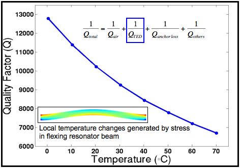
[9] B. Kim, et al., "Temperature Dependence of Quality Factor in MEMS Resonators," presented at Micro Electro Mechanical Systems, 2006, 19th IEEE International Conference on (MEMS '06). Istanbul, Turkey, 2006.
[10] M. A. Hopcroft, B. Kim, S. Chandorkar, R. Melamud, M. Agarwal, C. M. Jha, G. Bahl, J. Salvia, H. Mehta, H. K. Lee, R. N. Candler, and T. W. Kenny, "Using the temperature dependence of resonator quality factor as a thermometer," Applied Physics Letters, vol. 91, pp. 013505-3, 2007.
[11] W.-T. Hsu, et al., "Mechanically temperature-compensated flexural-mode micromechanical resonators," IEDM, 2000.
[12] Corning, Inc. Part C4700 Datasheet

Also see here for related publications.

This research is supported by the DARPA HERMIT Program


Top of Page

HOME

Kenny Group Research Projects

Page Created By:
Matt Hopcroft
Stanford University Department of Mechanical Engineering
Phone: (+1) 650-736-0044
Email: hopcroft at stanford dot edu
Page Updated: 18 October, 2007